70 kWh home battery: specifics
A closer look at the individual parts of the build.
Cell modules
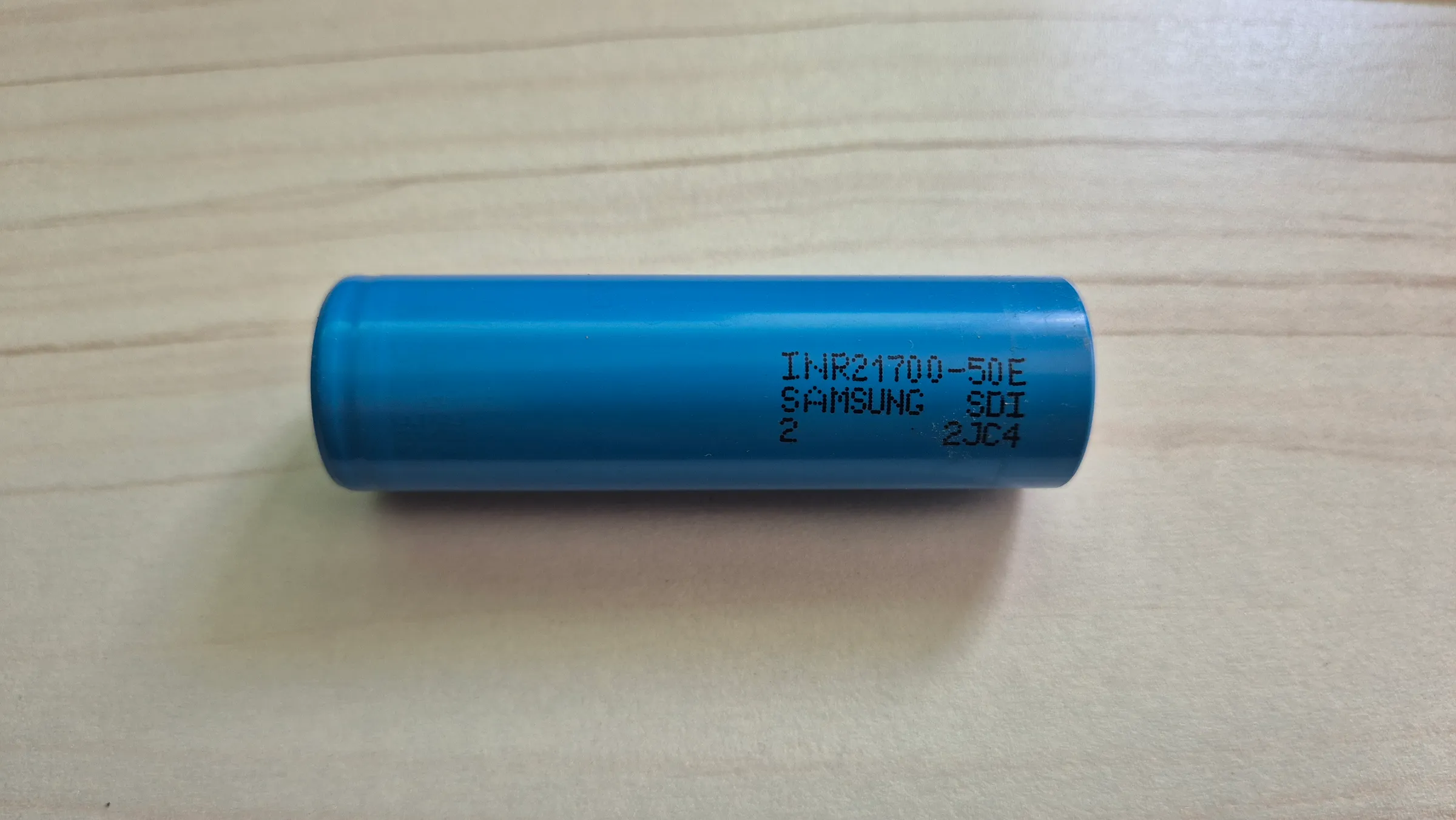
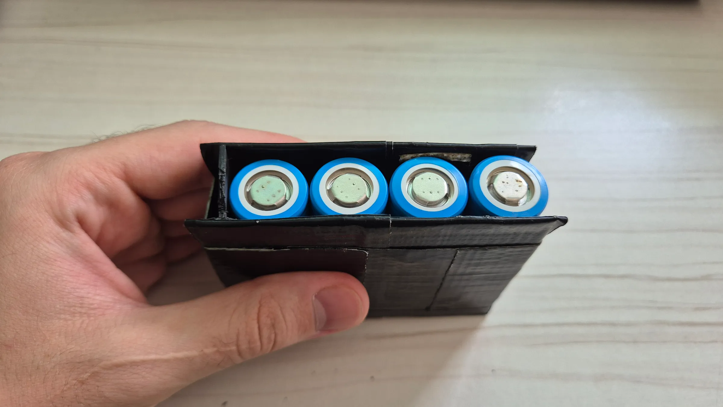
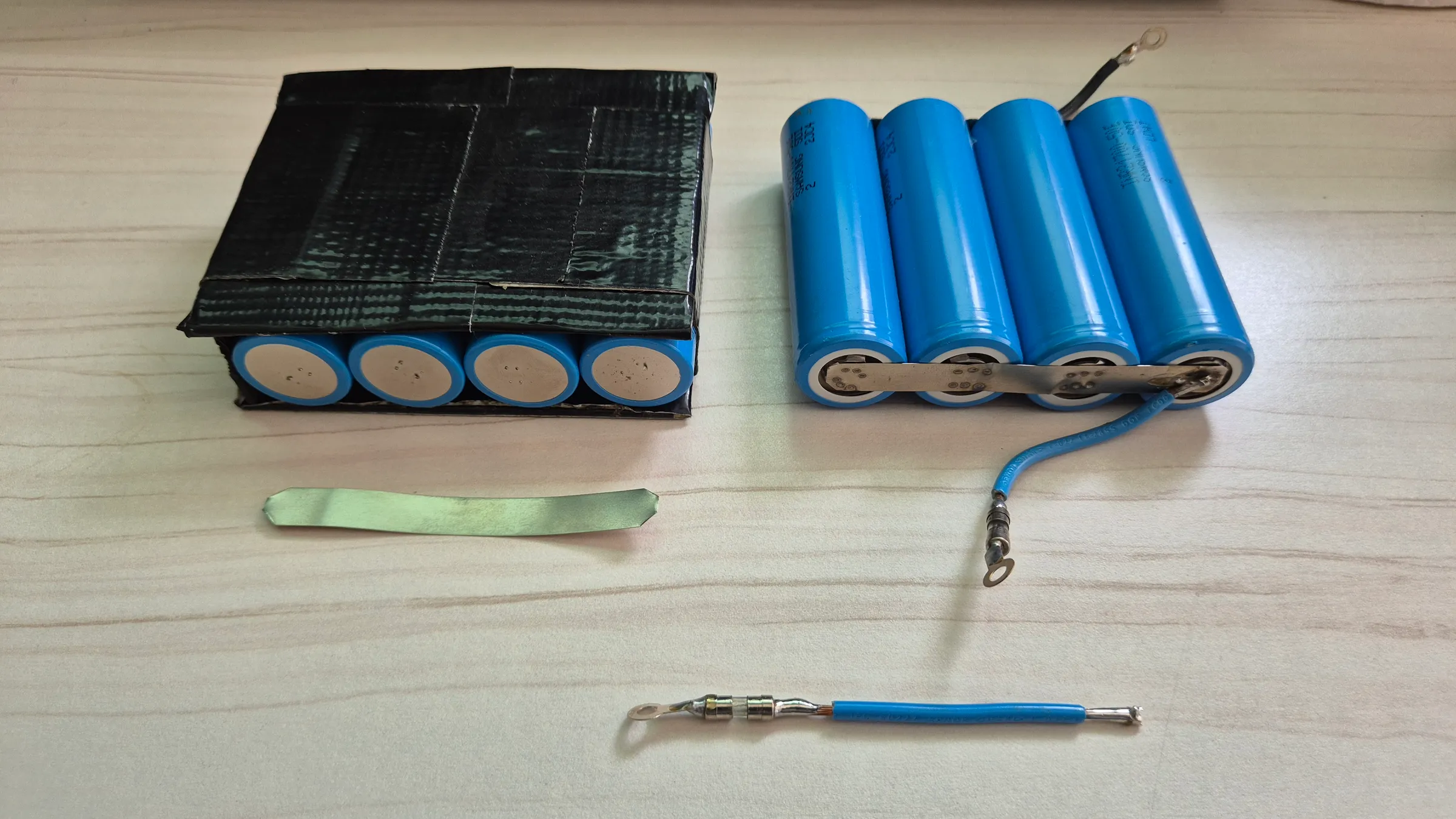
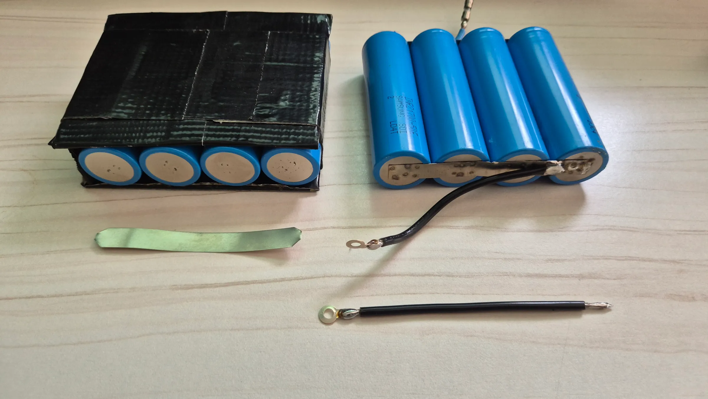
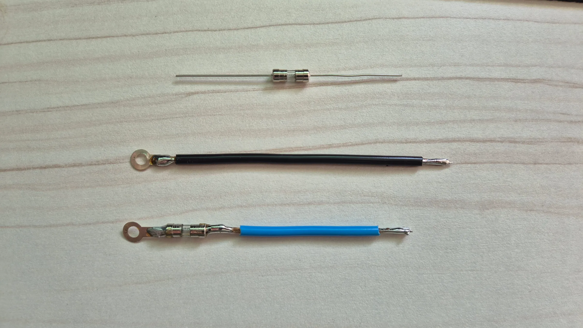
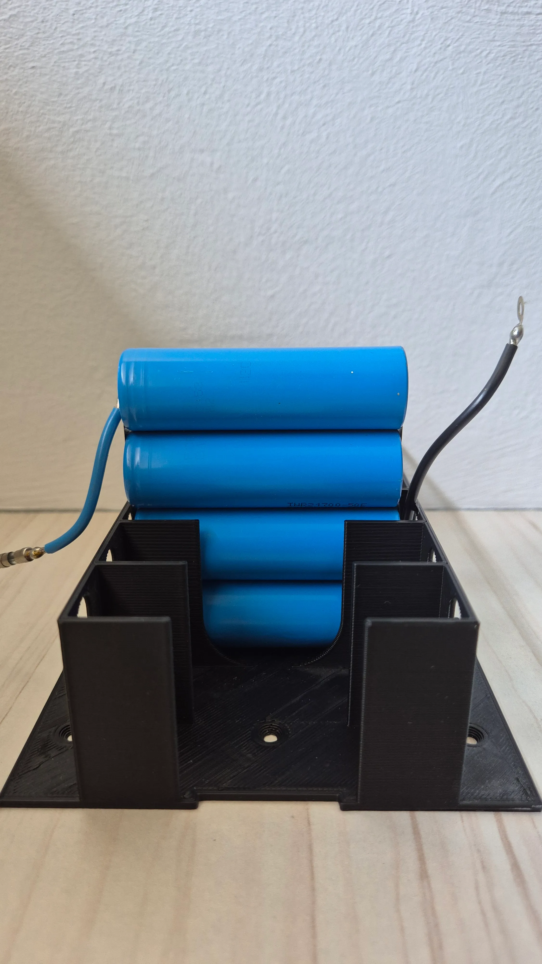
The battery pack is built around Samsung INR21700-50E cells arranged into distinct parallel groups, organized by rows of custom 3D-printed cell holders. Each individual holder is designed to accommodate seven independent modules cleanly, with each module consisting of four cells grouped in parallel (totaling 28 cells per holder). Within each four-cell module, the cells are interconnected using spot-welded nickel strips. Flexible leads are soldered to each side of the module, terminating in ring terminals that fasten directly to the busbars for straightforward assembly, inspection, and replacement. For localized safety, an inline fuse is integrated onto the positive lead of every individual four-cell module, ensuring any internal fault or short circuit is immediately isolated without affecting adjacent modules or the rest of the pack.
To assemble this many modules efficiently, I broke the build down into simple, highly repetitive batch operations.
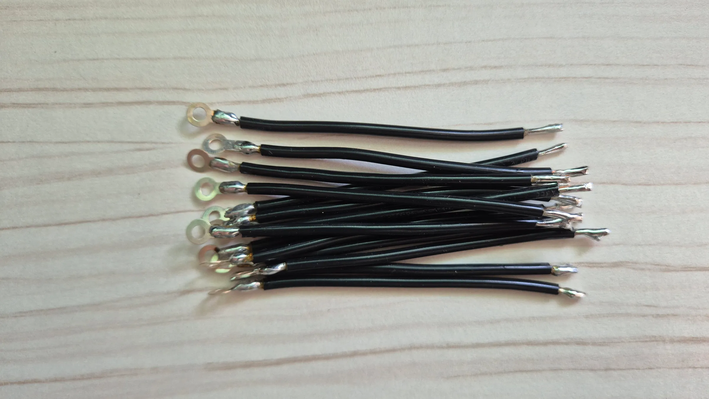
For the wiring, once I determined the exact lead lengths, I cut a master reference wire and used it as a guide to cut the rest without repeated measuring. After cutting and stripping every lead, I pre-tinned all the wire tips in one continuous pass until the full set was ready for assembly. Once the cell groups had their nickel strips spot-welded, attaching the leads was practically frictionless: grab a module, grab a pre-tinned lead, reflow the solder joint, and move directly to the next. Structuring the assembly into discrete, standardized tasks turned a tedious build into a fast, highly repeatable assembly line.
I learned an incredible amount throughout this entire build, and if I had to do it all over again, there are definitely a few things I’d change. That’s just the nature of prototyping: going through the process once shows you exactly where the bottlenecks are and how to save hours of effort next time. Top of that list? If you can, order your copper busbars pre-drilled. Trust me on that one 🤣.
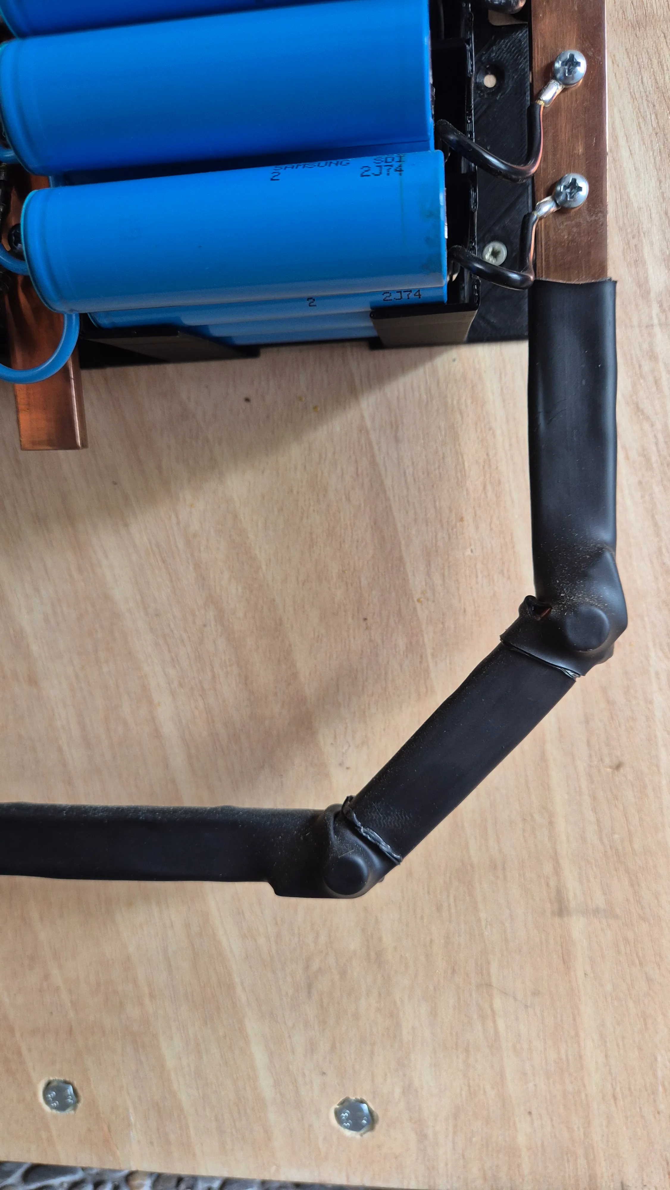
That batching is what the two photos below show: this is what a finished lead looked like, cut to length, stripped, tinned, and fitted with its fuse and terminal. I roughly prepared 300 this way before soldering a single one to a module.
3D-printed supports
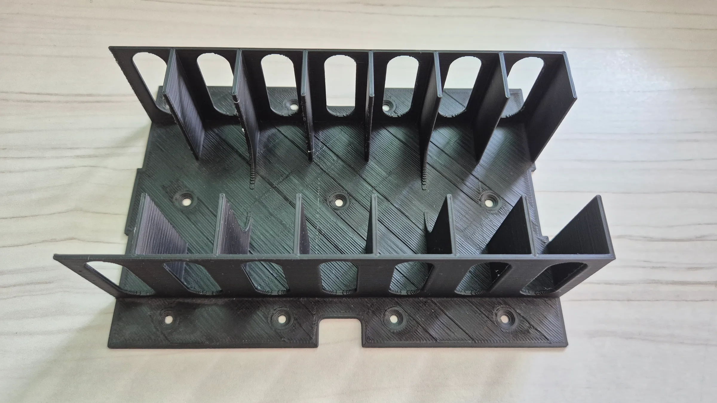
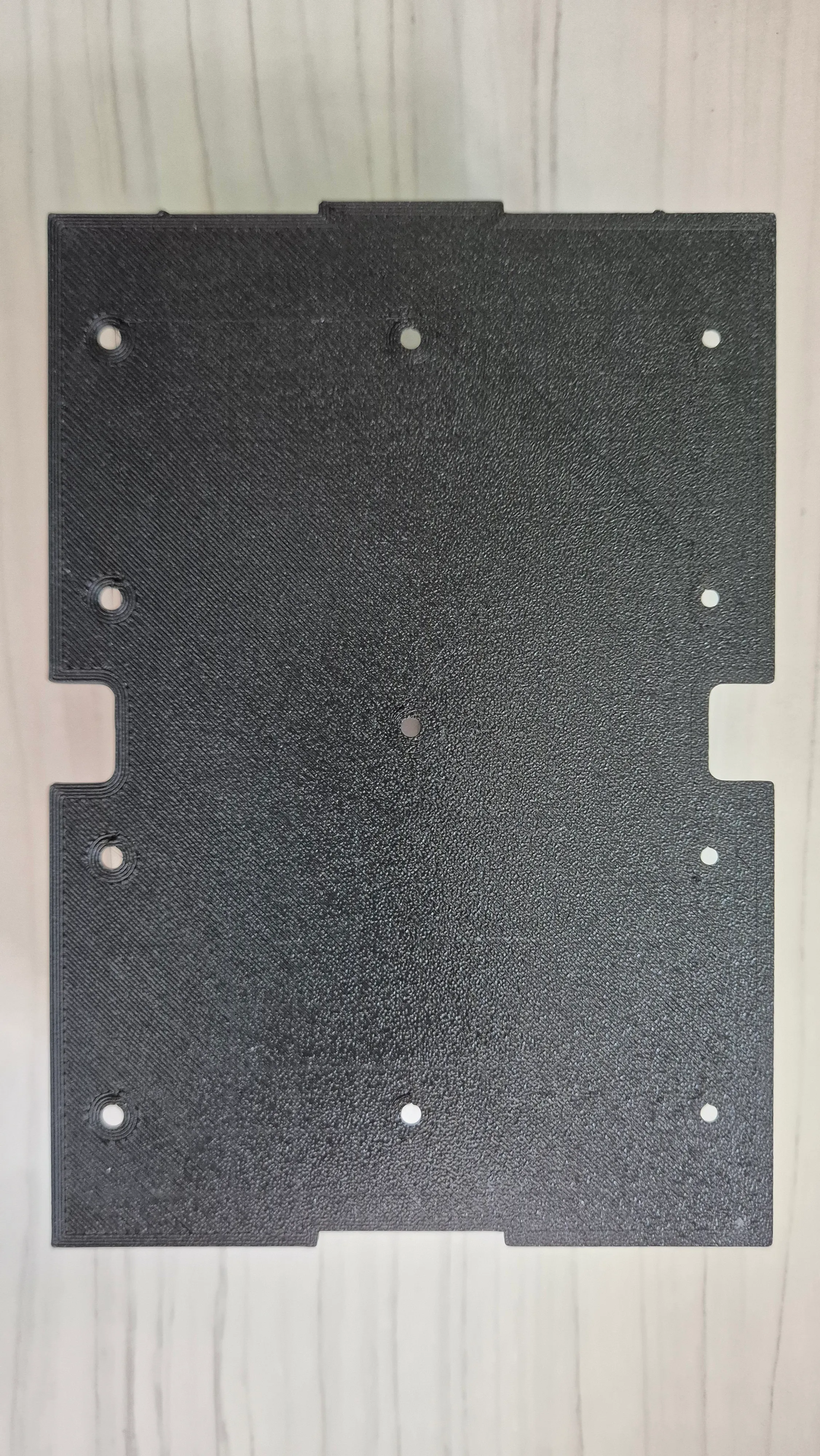
As I mentioned in the overview, my priority from the start was accessibility: I wanted to be able to add, remove, or swap modules and generally "debug" the pack at any point, not end up with one of those sealed packs you see in motorbikes or e-bikes that basically nobody ever opens again. That meant leaving the cells exposed rather than potting or fully enclosing them, an approach I didn't come up with myself: I'd seen a few functional prototypes online doing something similar and decided to go that route. This is really a mix of ideas I picked up and learned from other people's builds, so the credit isn't mine to take, just my own take on it.
The supports are designed to stack in both directions: horizontally to add columns, or vertically to add rows. For a 15S pack that works out to a 15×11 grid of 3D-printed supports, which took, as you'd expect, a very long time to print ((15*11*6h) / 24h = 41.25 days considering no failures).
Busbars & holders
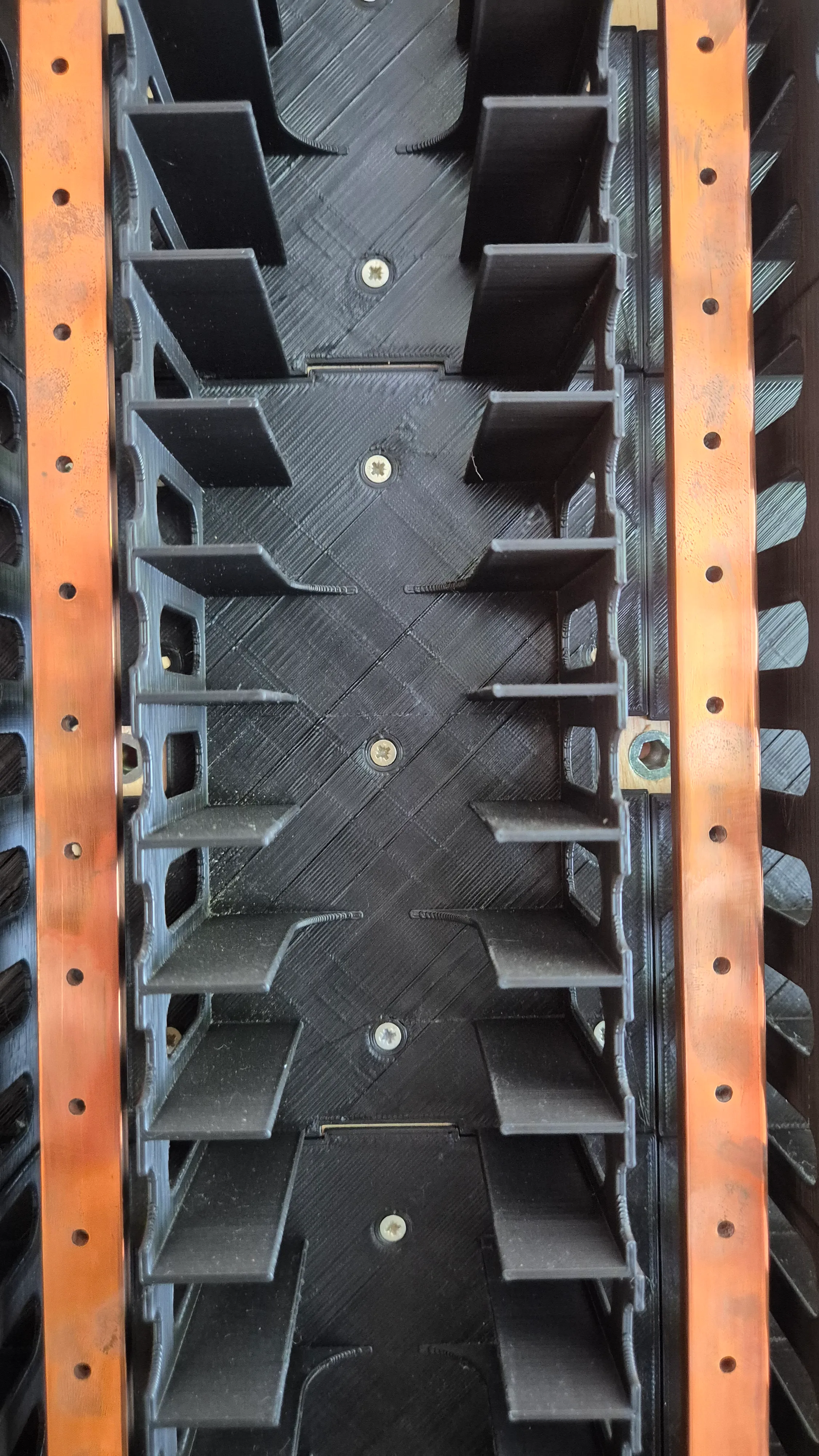
Copper busbars connect the modules of each series group and carry their combined current out to the rest of the pack. Each busbar sits in its own 3D-printed holder, which keeps it aligned with the cell terminals and isolated from its neighbors.
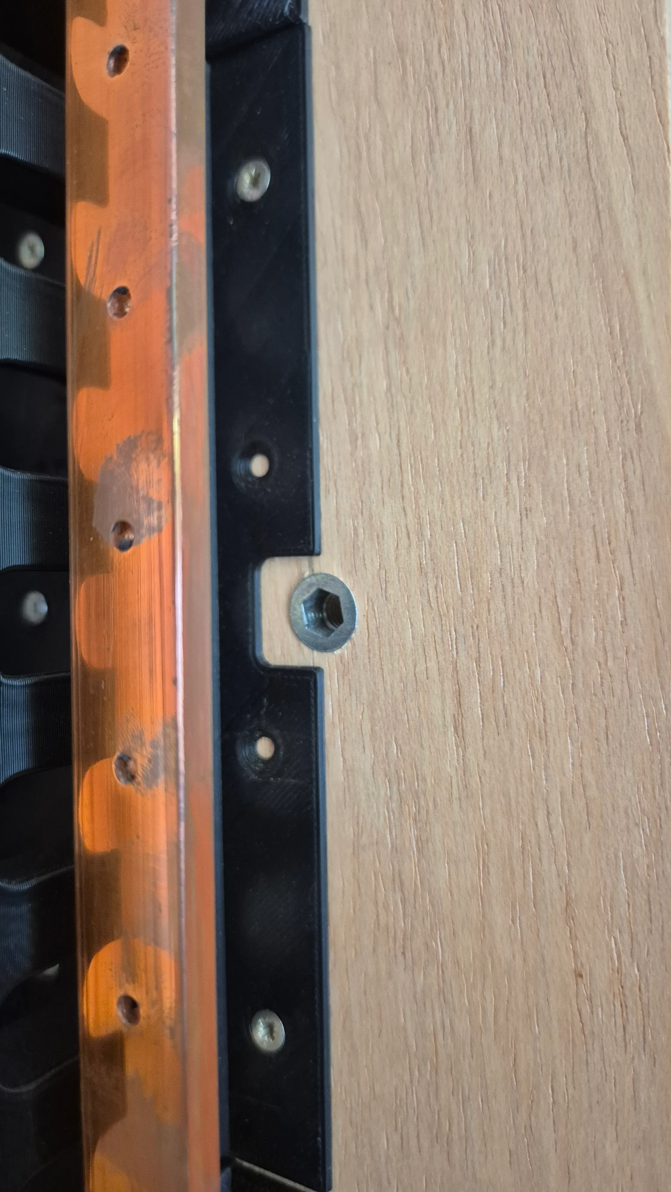
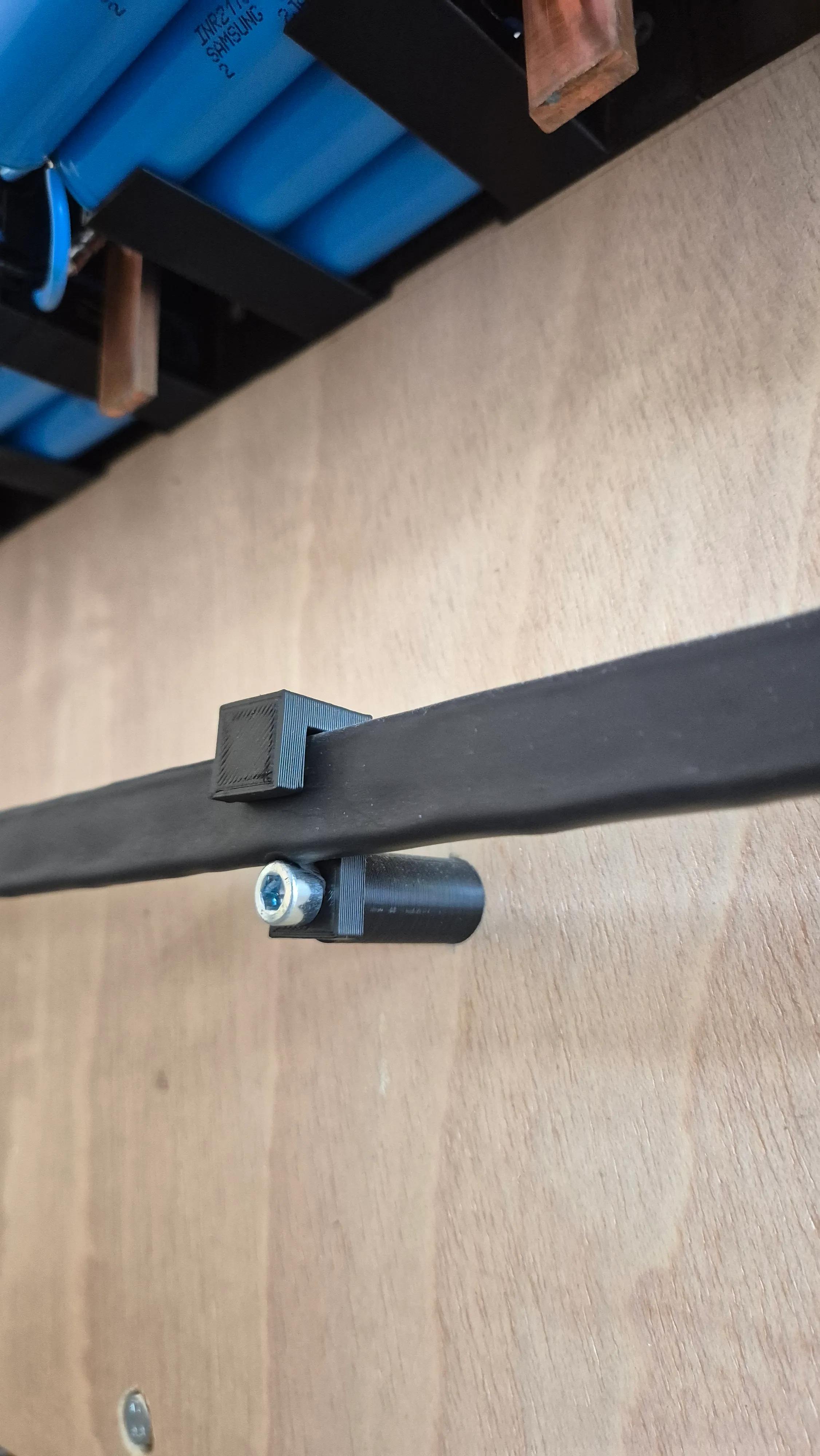
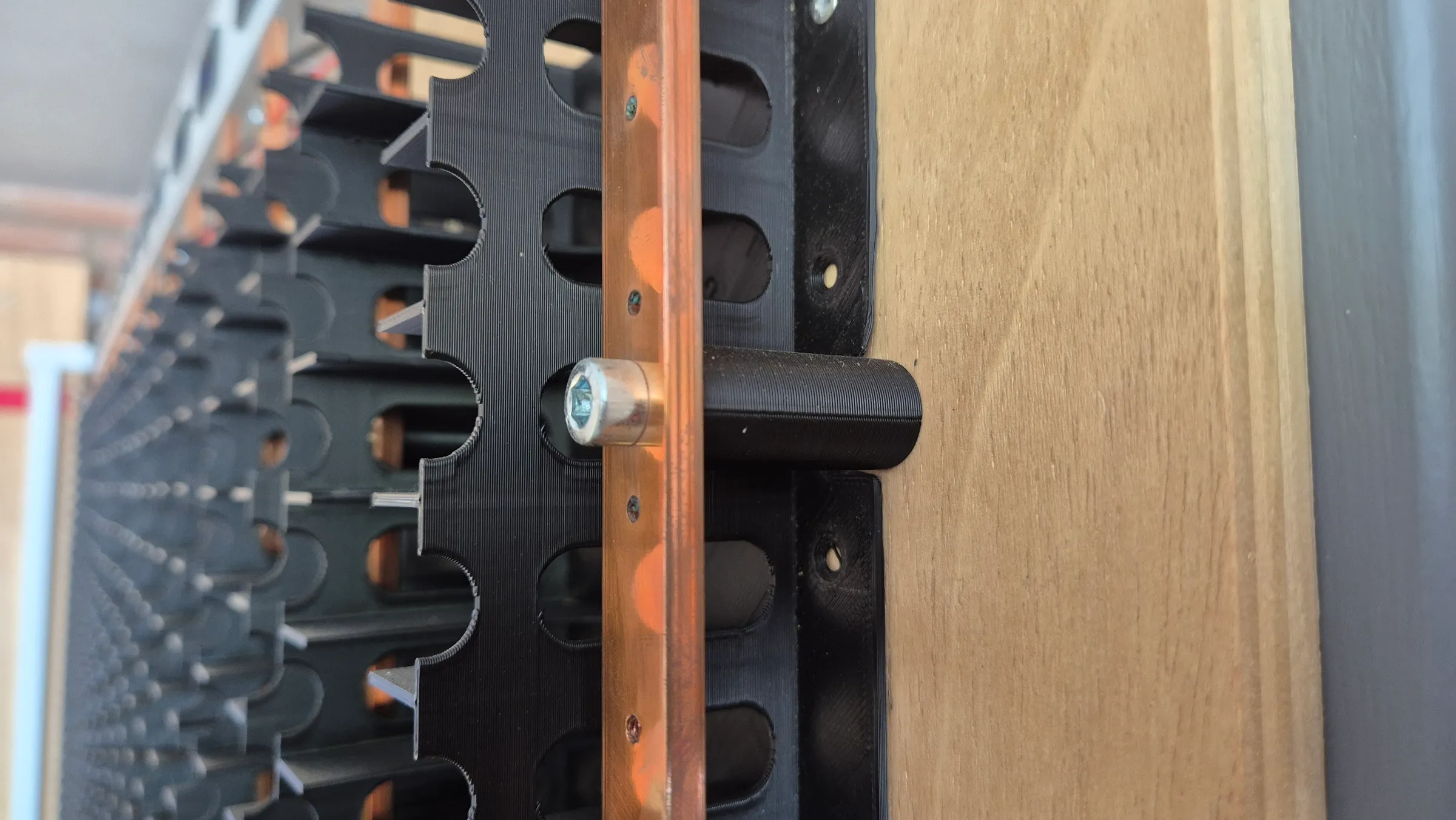
The holders don't sit flush against the wall: a second 3D-printed separator holds them a bit off it, so the whole row is "flying" rather than screwed straight to the surface. That gap makes it much easier to get a screwdriver in later to fasten the modules, and it keeps everything as far from any grounded surface as reasonably possible.
Each separator is anchored with screws driven into the wood behind it, and a second screw then goes into the first from the inside, which makes the whole assembly very firm and clean. Getting this right meant every hole had to line up: the screws in the wall and the holes in the busbar all had to be aligned with each other.
As you can see in some of the pictures, I initially thought I needed more support points, but I didn't end up using them. You can see them in the first and last photos in this section.
Safety
Safety is split across two layers here: passive protections that don't need anything actively watching them, and an active system that continuously supervises the whole pack.
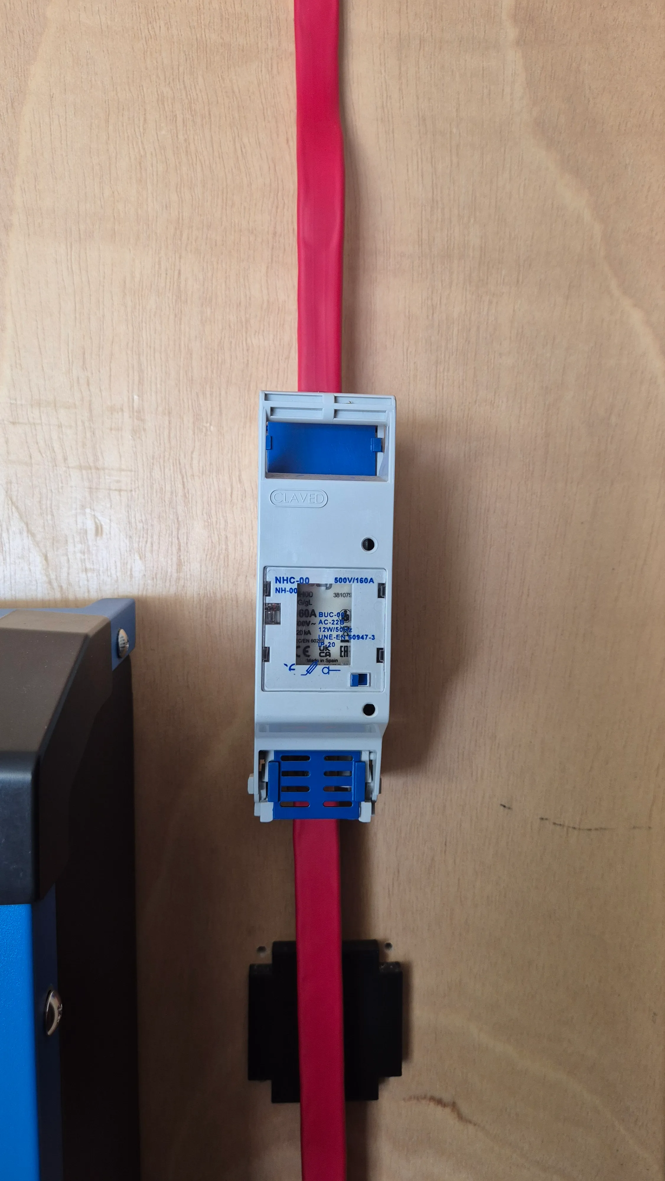
On the passive side, every module has its own fuse on its positive lead (shown earlier, in the cell modules section), so a fault in one group of four cells can't take down its neighbors. There's also a single main fuse protecting the battery as a whole.
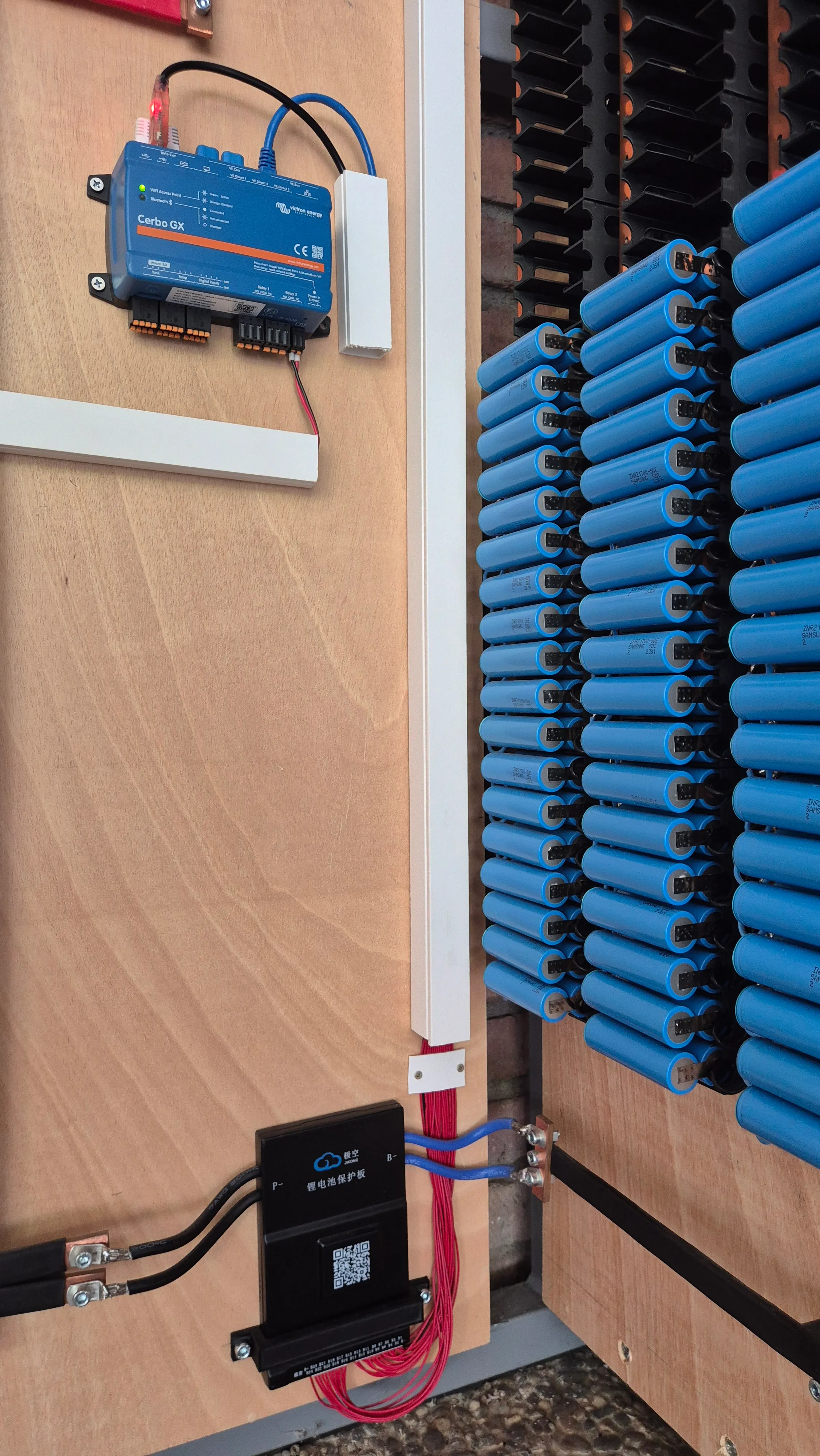
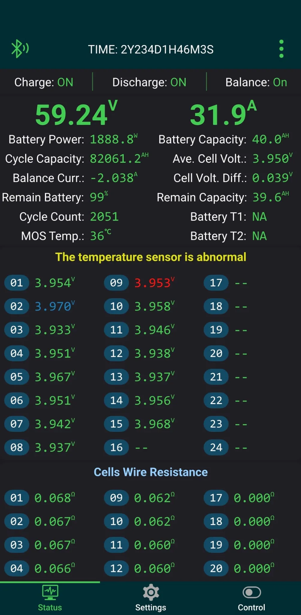
The active protection layer is managed by the Battery Management System (BMS). The unit continuously monitors cell health to enforce safe operational limits, preventing over-voltage during charging and under-voltage during discharge based on custom cutoff setpoints configured via the Bluetooth companion app.
A quick note on the companion app screenshot below: focus on the essentials rather than every single parameter. A few secondary telemetry fields were left at default values because they weren't required for this setup, so don't get bogged down by the unconfigured metrics.
What really matters is the row of individual series voltages. Notice how tightly matched they are across the board, with only millivolts of delta between them. The BMS actively balances the pack, redistributing or trimming charge across adjacent groups to prevent weak links from drifting out of alignment and degrading total usable capacity.
Monitoring
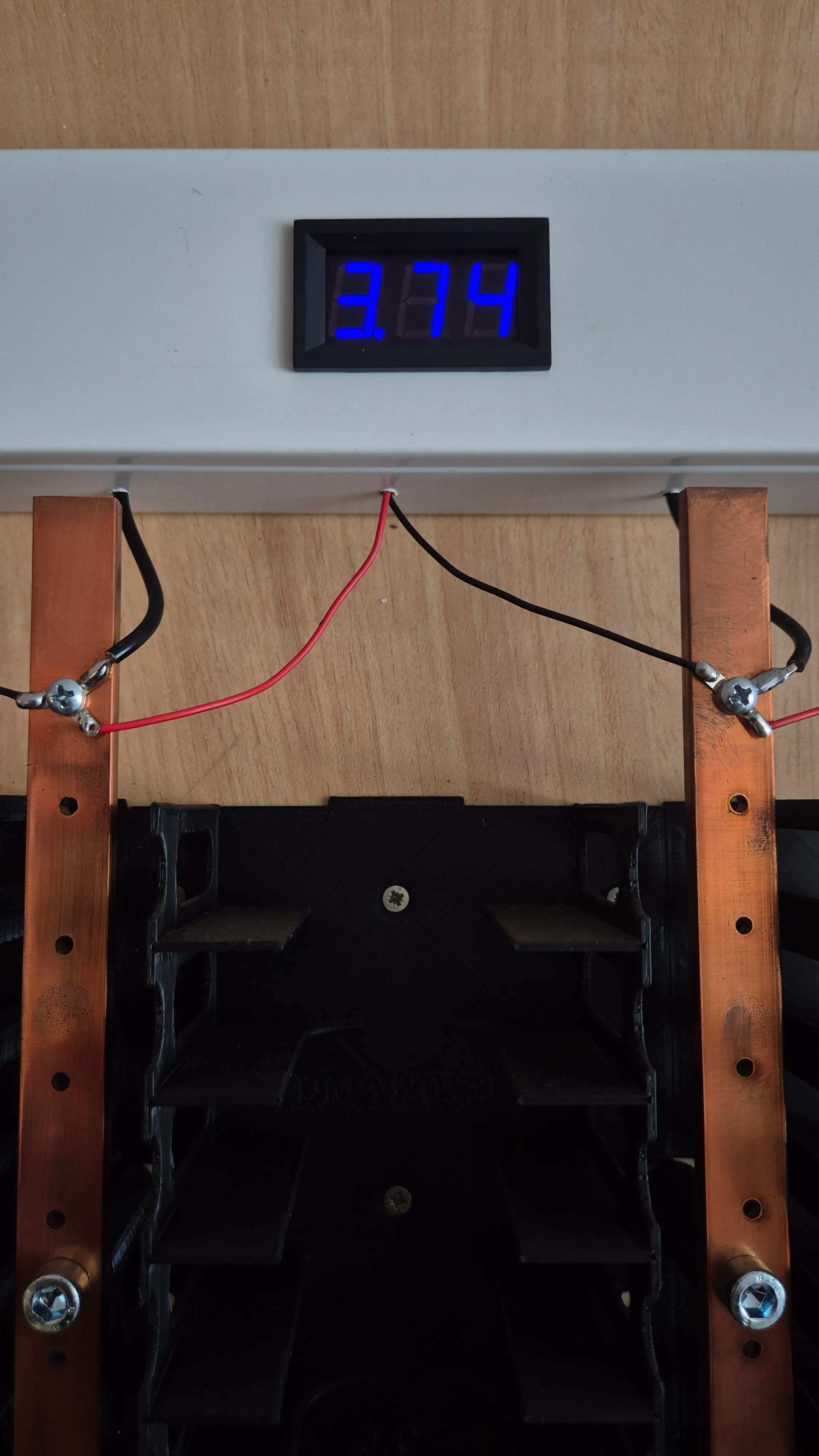
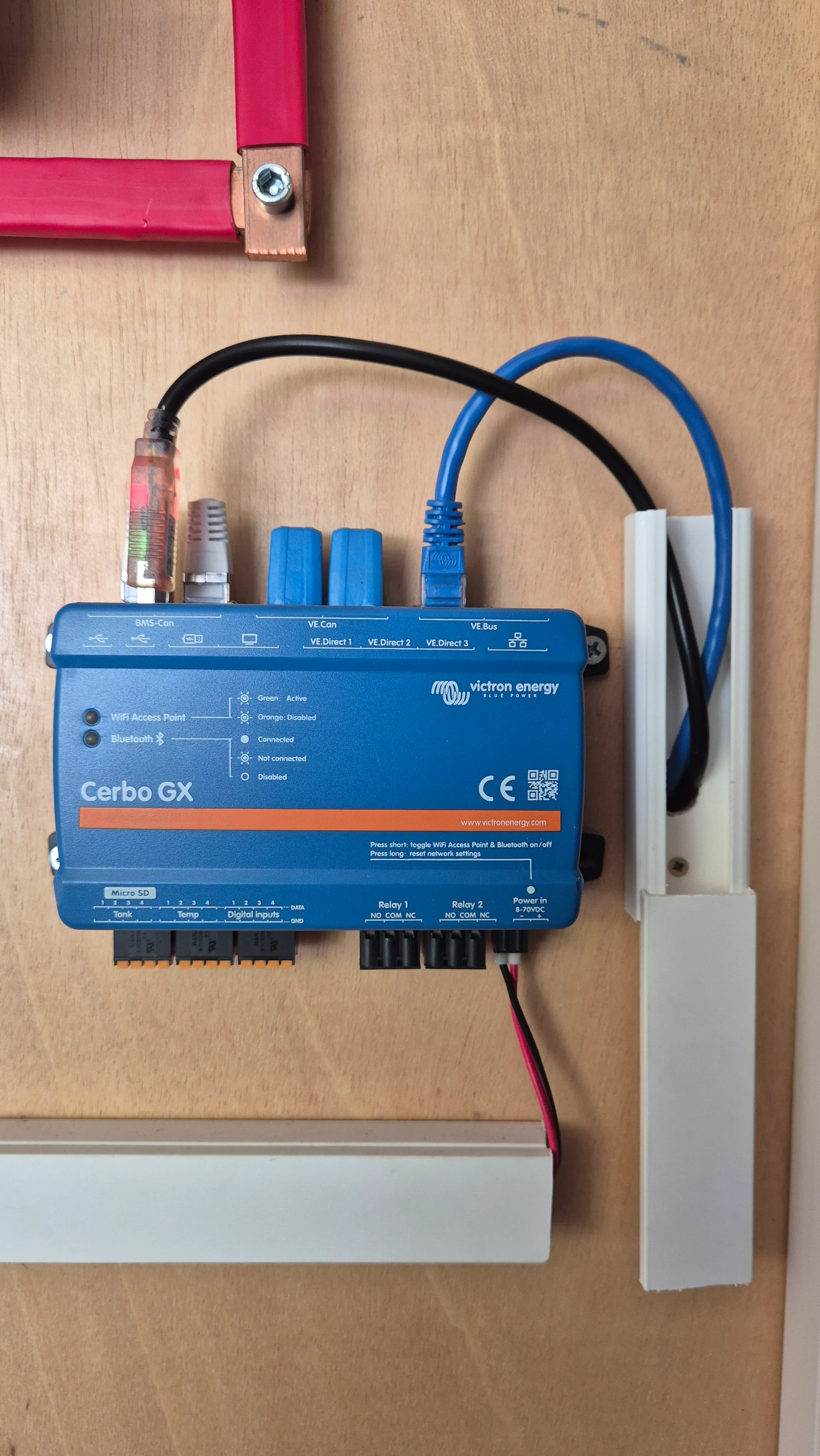
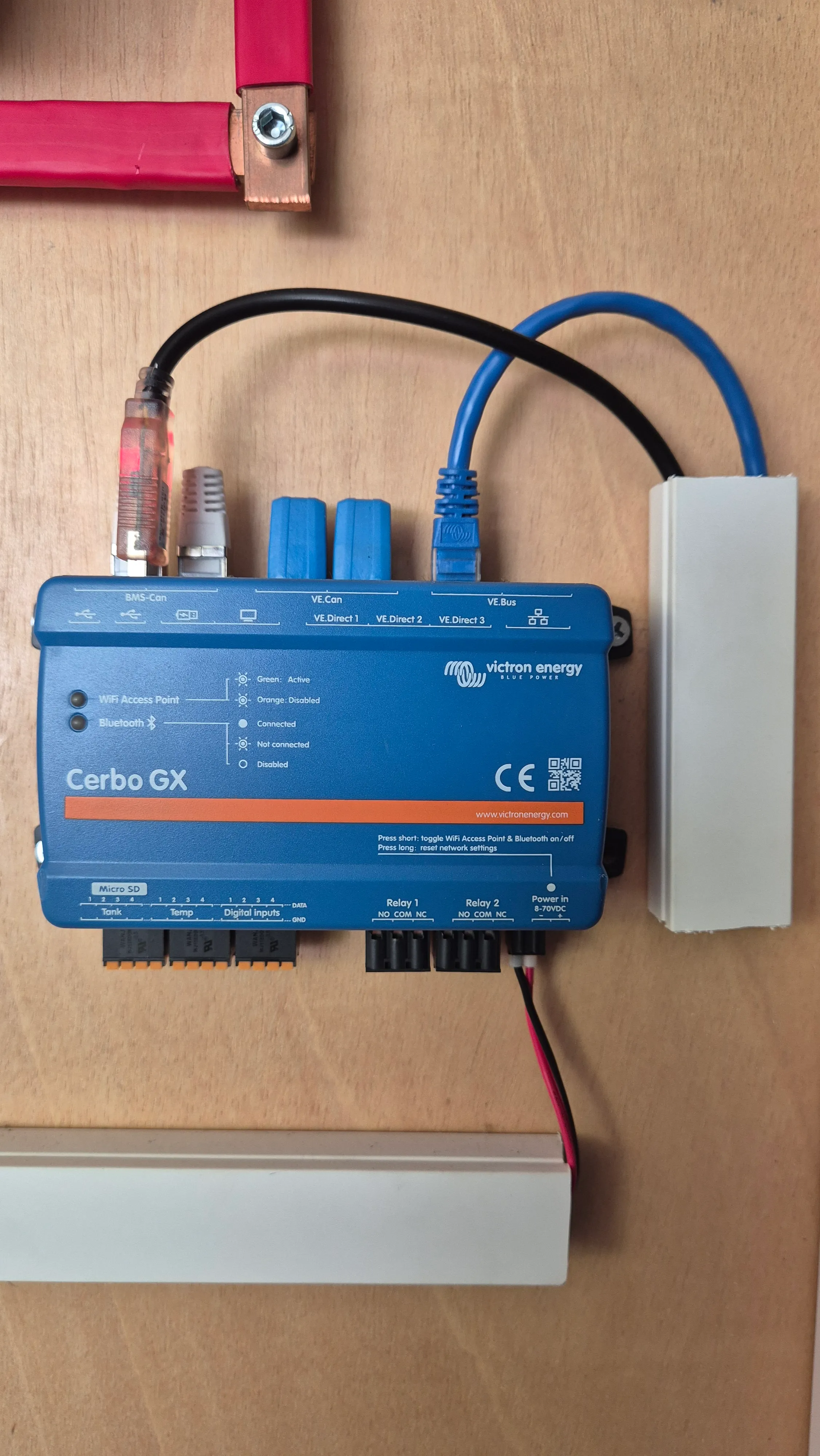
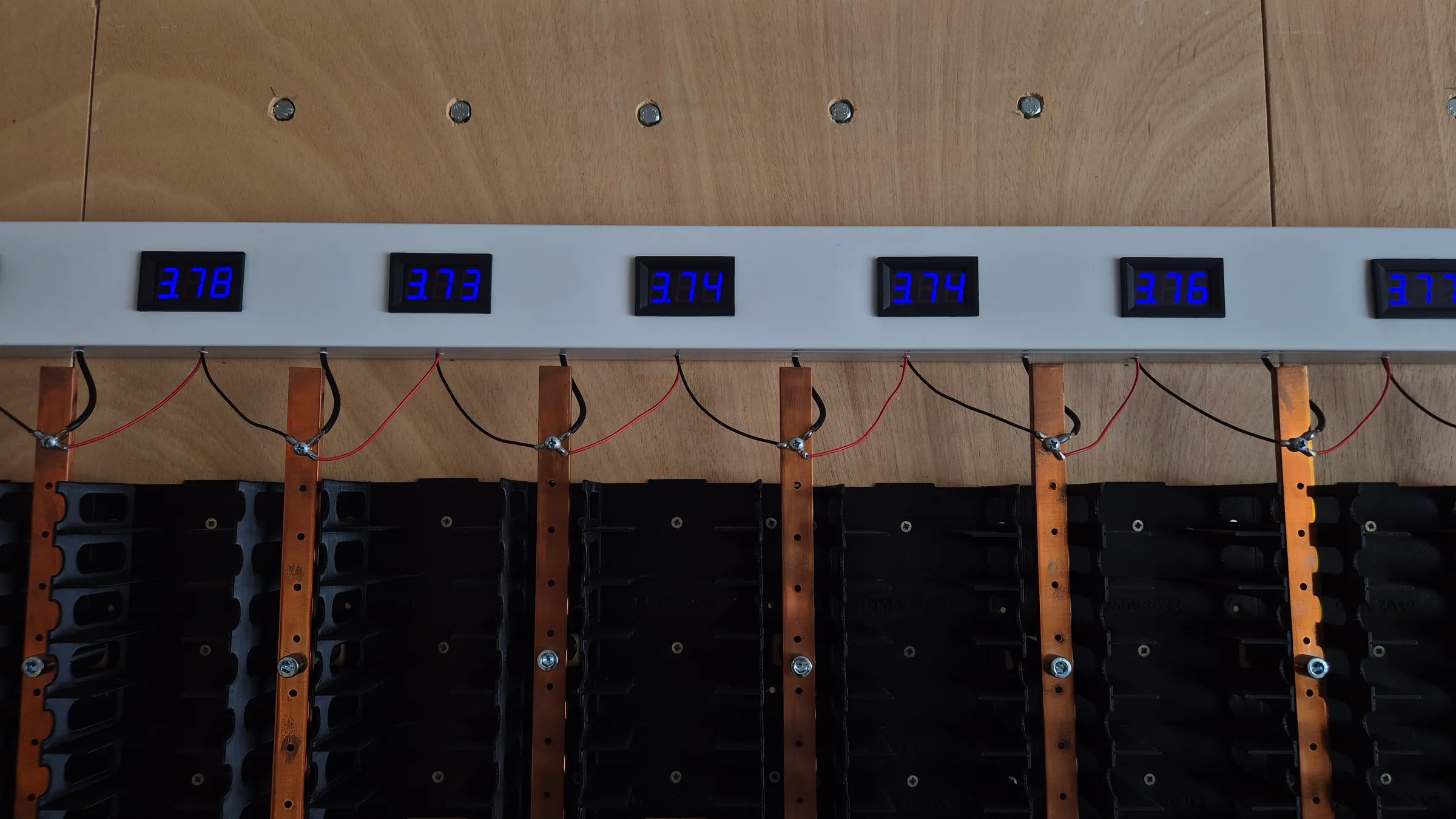
I wanted a way to visually see the current state of the battery at any time, so a clean idea was to put a display on each column reporting its voltage. In reality that's purely a visual aspect, it doesn't feed into anything, but it turned out very clean. The part actually in charge of monitoring everything, the MultiPlus and the house's current consumption, is the Cerbo GX: the main brain of this project.
Grid connection
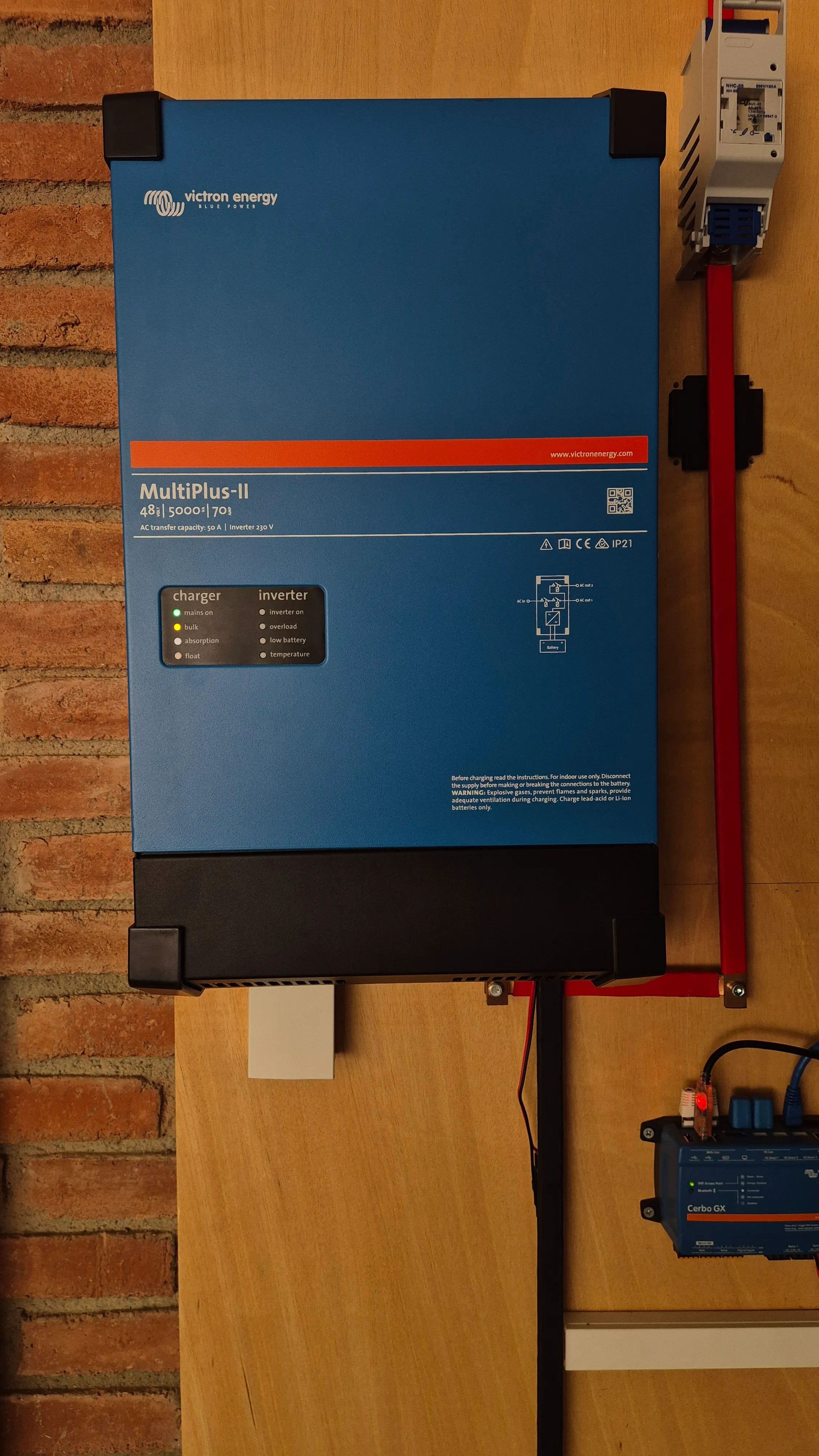
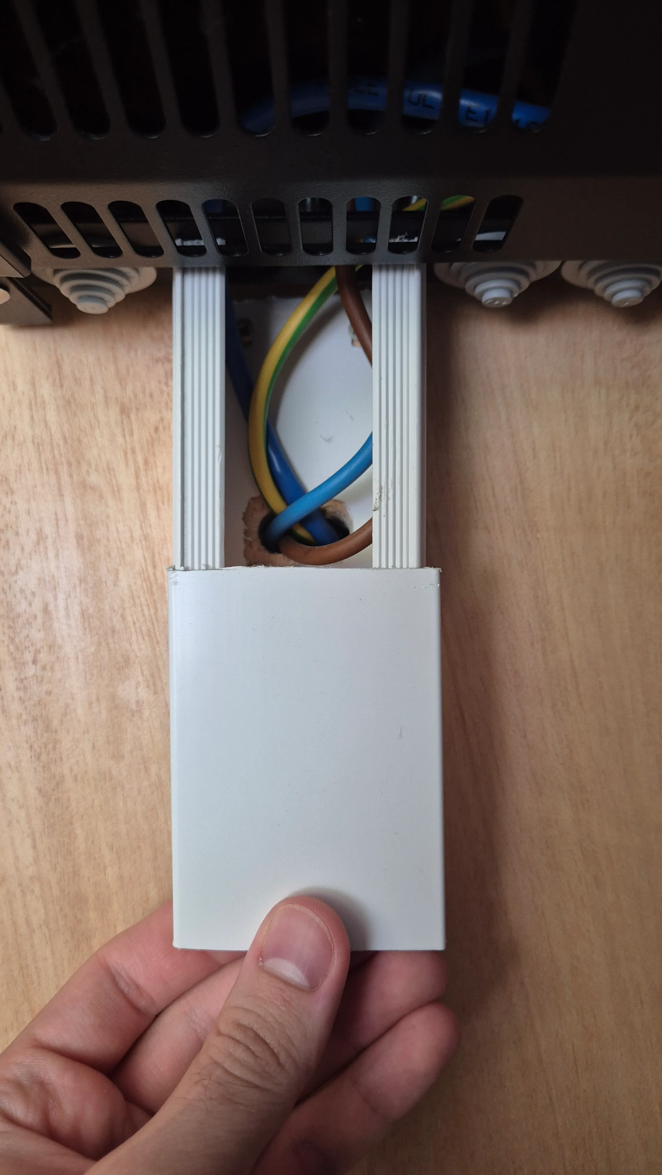
The system runs in parallel with the grid rather than as a switch-over backup. My Victron MultiPlus is rated for 5 kW, while the solar installation's own grid-tie inverter puts out up to 6 kW, so the MultiPlus can't be wired as a full bypass without capping what the panels are able to deliver. One consequence of that is that when the grid goes down, the battery system goes down with it, even though the panels would otherwise keep producing. It's possible to rewire the cables so the MultiPlus powers the house directly off-grid, but the parallel setup was the fastest and easiest way to get the system running, and that's the trade-off I chose for now.
I'm also aware this isn't the most efficient way to do it: the battery stores and releases energy as DC, so running it through the MultiPlus means a DC-to-AC conversion (and back, when charging) that wastes a percentage of energy that a more direct setup could avoid. But that's what I had, and it was the simplest option available at the time. MultiPlus units were quite expensive back then, and this is what the budget allowed. Even so, as you'll see in the next section, it works properly anyway.
Usage & consumption statistics
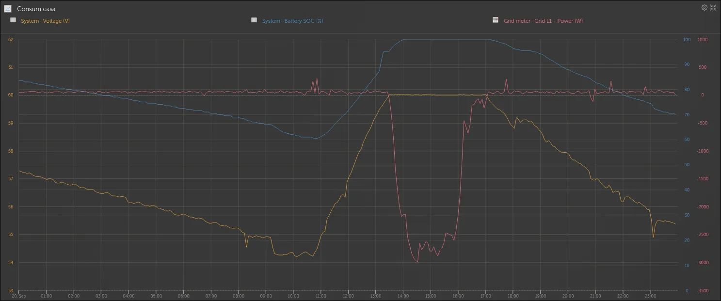
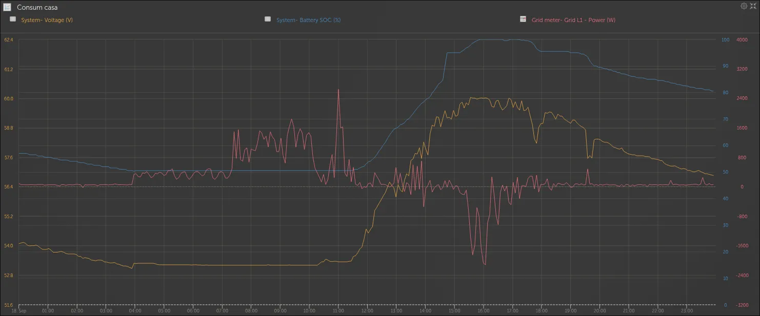
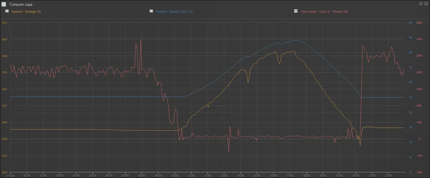
Once the system was running, I started pulling graphs from the Victron VRM dashboard to see how it actually behaves day to day. The main thing to look at is the orange line: the battery's voltage, read off the left axis, which is what tells you the state of the battery. The red line is the house's consumption, in watts, read off the right axis.
A summer day looks like the graph below. House consumption sits around 50 W for most of the day, and once the battery is full while the panels are still producing more than the house needs, that surplus is sent to the grid instead. That's why the red line goes negative there: negative just means the power is flowing the other way, out to the grid rather than in from it.
That's how a good, sunny summer day looks, but in reality the average day looks closer to the one below, with some clouds passing through. The battery still carries the house through the evening, but once it runs out around midnight, consumption switches back to the grid.
A much more interesting scenario is a day when the EV is plugged in all day. As the telemetry shows, we rely on the grid or pack until the solar array ramps up. Midday sun covers the vehicle’s draw and even routes surplus power back into the home storage pack. That surplus window is short-lived, though as soon as solar generation dips, the car immediately pulls hard from the home battery again. Considering the EV carries an 80 kWh pack of its own, it dwarfs the home setup and can drain our reserves in no time.
If there's one thing this project has made clear, it's that the next step should be adding more solar panels before adding more cells. You can store as much energy as you want, but it doesn't matter if you're not producing enough to fill it in the first place.